
")
")
A truss bridge is a bridge whose load-bearing superstructure is composed of a truss, a structure of connected elements forming triangular units. The connected elements (typically straight) may be stressed from tension, compression, or sometimes both in response to dynamic loads...
Description
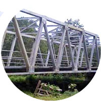
A truss bridge is a bridge whose load-bearing superstructure is composed of a truss, a structure of connected elements forming triangular units. The connected elements (typically straight) may be stressed from tension, compression, or sometimes both in response to dynamic loads. Truss bridges are one of the oldest types of modern bridges. The basic types of truss bridges shown in this article have simple designs which could be easily analyzed by 19th- and early 20th-century engineers. A truss bridge is economical to construct because it uses materials efficiently.
The nature of a truss allows the analysis of the structure using a few assumptions and the application of Newton's laws of motion according to the branch of physics known as statics. For purposes of analysis, trusses are assumed to be pin jointed where the straight components meet. This assumption means that members of the truss (chords, verticals and diagonals) will act only in tension or compression. A more complex analysis is required where rigid joints impose significant bending loads upon the elements, as in a Vierendeel truss.
In the bridge illustrated in the infobox at the top, vertical members are in tension, lower horizontal members in tension, shear, and bending, outer diagonal and top members are in compression, while the inner diagonals are in tension. The central vertical member stabilizes the upper compression member, preventing it from buckling. If the top member is sufficiently stiff then this vertical element may be eliminated. If the lower chord (a horizontal member of a truss) is sufficiently resistant to bending and shear, the outer vertical elements may be eliminated, but with additional strength added to other members in compensation. The ability to distribute the forces in various ways has led to a large variety of truss bridge types. Some types may be more advantageous when wood is employed for compression elements while other types may be easier to erect in particular site conditions, or when the balance between labor, machinery and material costs have certain favorable proportions.
The inclusion of the elements shown is largely an engineering decision based upon economics, being a balance between the costs of raw materials, off-site fabrication, component transportation, on-site erection, the availability of machinery and the cost of labor. In other cases the appearance of the structure may take on greater importance and so influence the design decisions beyond mere matters of economics. Modern materials such as prestressed concrete and fabrication methods, such as automated welding, and the changing price of steel relative to that of labor have significantly influenced the design of modern bridges.


Specification
| Description | A - Class Bridge Standard Data | B - Class Bridge Standard Data | C-Class Bridge Standard Data | |||||||||||||
| Bridge Type | A-40 | A-45 | A-50 | A-55 | A-60 | B-40 | B-45 | B-50 | B-55 | B-60 | C-35 | C-40 | C-45 | C-50 | C55 | C-60 |
| Bridge Span | 40M | 45M | 50M | 55M | 60M | 40M | 45M | 50M | 55M | 60M | 35M | 50M | 45M | 50M | 55M | 60M |
| Bridge Width | 9 M | 7M | 5,5M | |||||||||||||
| Road Width | 7 M | 6 M | 4,5 M | |||||||||||||
| Pedestrian | 2 x 1 M | 2 x 0.5 M | 2 x 0.5 M | |||||||||||||
| Design Specification | RSNI T-03-2005, AASHTO, AISC | |||||||||||||||
| Loading Specification | RSNI-T-02-2005 | |||||||||||||||
| Material Specification | Steel: JIS SM 490 (Main Structure), JIS SS 400 or equivalent | |||||||||||||||
| Connection : F 10T JIS B1186, JIS Grade 4.8 Bolt | ||||||||||||||||
| Coating : Galvanizing min 80 micron thick | ||||||||||||||||


